APPLICATIONS OF DEFORMATION-MECHANISM MAPS
19.1 Uses of the Maps
19.2 Case Study: The Creep of Lead Water Pipes
19.3 Case Study: The Creep of 316 Stainless Steel in a Fast Nuclear Reactor
19.4 Case Study: Creep of a Superalloy Turbine Blade
19.5 Case Study: The Creep of Tungsten Map Filaments
19.6 Case Study: Metal-Forming and Shaping
19.7 Case Study: Creep in the South Polar Ice Cap
19.8 Case Study: The Rheology of the Upper Mantle
-
Pressure, temperature, stress and strain-rate in the upper mantle
-
Deformation maps for olivine, including the effects of pressure
THE MAPS summarize, in a compact way, information about steady state and transient flow in a material. They can be used in the ways listed below. Each is illustrated by one of more of the case studies.
(a) They can be used to identify the mechanism by which a component or structure deforms in service, thereby identifying the constitutive law or combination of laws that should be used in design. Examples are given in the first three case studies: the lead pipe, the reactor components and the turbine blade. In particular, they can help in geophysical modelling as illustrated by the case studies of the polar ice cap and earth's upper mantle.
(b) They can be used to estimate approximately and quickly, the strain-rate or the total strain (both transient and steady state) of a component in service; the case studies of the reactor components and of the tungsten lamp filaments are examples.
(c) They can give guidance in alloy design and selection. Strengthening methods are selective: alloying, for instance, may suppress power-law creep but leave diffusional flow unchanged; increasing the grain size does the opposite. By identifying the dominant mechanism of flow, the maps help the alloy designer make a rational choice. The case studies of the lead pipes and of the turbine blades contain examples.
(d) They help in designing experiments. The ideal experimental conditions for studying a given mechanism can be read directly from even an approximate map—and the existence of isomechanical groups (Chapter 18) allows the construction of a rough map for almost any pure materials.
(e) Finally, they have pedagogical value in allowing a body of detailed information to be presented in a simple way. Each map is a summary of the mechanical behaviour of the material, and (because of the normalized axes) also gives an approximate description of other related materials with similar bonding, crystal structure and purity (Chapter 18). The regime in which a structure operates, or a process takes place, can conveniently be illustrated on the maps: the case study of metal forming operations is an example, and the maps bring out the fundamental differences and similarities between the materials.
Most practical problems in plasticity and creep involve multiaxial states of stress and of strain-rate. All the maps shown here have been plotted in a way which allows their use when this is so. The stress axis is that of equivalent shear stress:
|
|
(19.1) |
and the contours are those of equivalent strain-rate.
|
|
(19.2) |
Here,
σ1,
σ2, σ3,
and
![]() ,
,
![]() ,
,
![]() are the
principal stresses and strain rates and Sij is the deviatoric part of the stress
tensor:
are the
principal stresses and strain rates and Sij is the deviatoric part of the stress
tensor:
|
|
The maps show the
relationship between ![]() : they are a picture of the
constitutive relations. The case study of 316 stainless steel contains
examples of the use of eqns. (19.1) and (19.2), and shows how, if the two
variables (in this case,)
: they are a picture of the
constitutive relations. The case study of 316 stainless steel contains
examples of the use of eqns. (19.1) and (19.2), and shows how, if the two
variables (in this case,) ![]() are known, the map gives a third
are known, the map gives a third ![]() . The individual
components of strain-rate are recovered by applying the Levi Mises, or
Associated Flow, Rule, which for our purposes is best written as:
. The individual
components of strain-rate are recovered by applying the Levi Mises, or
Associated Flow, Rule, which for our purposes is best written as:
|
|
(19.3) |
or, equivalently,
|
|
The case studies follow a standard procedure that we have found to work well. It is as follows.
First, analyse the
mechanics of the sample, component, or structure, tabulating the normalized
stress (σs/μ) homologous
temperature (T/TM) or
strain-rate (![]() ) to which it is subjected. In some
instances all three are uniquely determined. More frequently they vary with
position (as in the case study of the lead pipe and of the Polar ice cap) or
with time (as with the turbine blade): then the ranges of stress, temperature
and strain-rate should be tabulated.
) to which it is subjected. In some
instances all three are uniquely determined. More frequently they vary with
position (as in the case study of the lead pipe and of the Polar ice cap) or
with time (as with the turbine blade): then the ranges of stress, temperature
and strain-rate should be tabulated.
Second, select or construct a map for the material of which the sample or part is made, with the appropriate grain size. Maps for some 40 materials are given in this book. Often, however, the material is one for which no map exists. Then, ideally, a map should be constructed, using the methods described in Chapter 3. But it is frequently adequate to start with the data for the pure base metal or ceramic— nickel for example—and modify those parts of it required to make the map fit experimental data for the alloy—Monel (Ni-30% Cu) for instance. To a first approximation, the lattice parameter, moduli and diffusion coefficients can be left unchanged, and the glide and creep data modified to fit experiment, though at a more precise level all would be modified. If little or no data are available (as is frequently the case for ceramics) an approximate map can sometimes be prepared by using the existence of isomechanical groups (Chapter 18), adjusting the map to fit limited data where they exist.
Third, plot the range of conditions of the sample or part onto the map. If the range of stress, temperature and strain-rate (or strain) are all known, an immediate check for consistency is possible. The lead-pipe study contains an example of this check.
Fourth, read off the
mechanisms of flow, thus determining the appropriate constitutive law or
combination of laws for design or modelling. If only two of the three
variables ![]() are
known, use the map to determine the third. Maps for the same material with
another grain size, or for a new material, can be used to examine how these
changes might affect the deformation of the component, leading to the
selection of an appropriate material.
are
known, use the map to determine the third. Maps for the same material with
another grain size, or for a new material, can be used to examine how these
changes might affect the deformation of the component, leading to the
selection of an appropriate material.
At this stage a material has been chosen, the dominant deformation mechanism (and thus constitutive law) identified, and the approximate deformation rate determined. If design looks feasible, a detailed stress analysis of the sample or part should now be carried out, using the proper constitutive law fitted to data covering the range of operation of the part for the specific material, or batch, of which it is to be made. These may have to be requested from suppliers, or determined by specially commissioned tests.
The maps, then, should be used as the first phase of a design procedure only; but they allow this phase to be carried out very quickly and cheaply. Be cautious of attributing too much precision to the maps. They are only as good as the equations and data used to construct them—and both are often poor. An idea of the uncertainty can often be obtained from the data plots, of which many can be found in earlier chapters: the scatter in the data gives a measure of the batch-to-batch variation in material properties.
19.2 CASE STUDY: THE CREEP OF LEAD WATER PIPES
The first case study illustrates the use of deformation maps to identify the dominant mechanism of flow, and to prescribe a strengthening mechanism— in this instance, an increase in grain size—which will reduce its rate.
Since pre-Roman times lead has been used for water conduits and roof coverings. In England it has been common to use "soft lead" for these purposes: typically 99.5% lead containing a little Sb, Sn and lesser quantities of As, Cu, Ag, Fe and Zn, although elsewhere in Europe, particularly Germany, a "hard lead" containing 1 to 6% Sb was used. The corrosion resistance, ease of forming and welding, sound-absorbing properties and attractive appearance recommend lead for many exterior purposes—but it creeps at a rate which becomes alarming above 50°C. Even at room temperature (0.5 TM) lead creeps (Fig. 19.1).
The earliest pipes and roofing sheet were cast. Even today, lead sheet is cast on a sand bed to a uniform thickness of about 3 mm for cathedral roofs; and lead down-spouting and piping is cast in sections for building use. This cast material has a large grain size (greater than 1 mm) and—for reasons which will become apparent—is much more creep-resistant than the cheaper extruded pipe and rolled sheet introduced in Victorian times. The plastic deformation involved in these forming processes makes the lead recrystallize, giving a much smaller grain size (10–100 µ) which, in commercial alloys, is stabilized by non-metallic inclusions and precipitates of an antimony-rich phase.
There is considerable evidence that a coarse grain size greatly reduces the creep rate. Pressurized lead pipe swells at the places where the grain size is finest (Hofmann, 1970, p.435) [1]. Pure lead, and a number of its dilute alloys, show a strong inverse dependence of creep-rate on grain size at slow strain-rates (Hopkins and Thwaites, 1953) [2]; and these strainrates are proportional to stress (Hofmann, 1970, p. 237) [1], both observations suggesting diffusional flow.
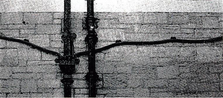
Fig. 19.1 Lead pipes on a 75-year-old building in southern New England. The creep-induced curvature of these pipes is typical of Victorian lead water piping.
Given sufficient time, a Victorian lead pipe supported at discrete points along its length will sag under its own weight (Fig. 19.1). By what mechanism does this creep occur? And why is it that Roman lead ducting and piping, despite its greater age, does not appear to have sagged in this way?
We have examined two
examples of creeping lead pipes: one an external drain pipe, 75 years old; the
other, an interior hot-water pipe, aged about 70 years. Both had a grain
size of about 50 µm. They are sketched in Fig. 19.2. The maximum strain is in
the lower surface of the pipe; it can be calculated from the radius of
curvature (R), the depth of the sag (h), the length (1)
and the height (b) of the pipe. The average creep rate is given by
dividing this by the life (t) of the pipe, and multiplying by √3
to convert to an equivalent shear strain-rate ![]() . For small sags (h
< b), the result is
. For small sags (h
< b), the result is ![]() . Applying this to the pipes of Fig.
19.2 gives the approximate strain-rates listed in Table 19.1. They are
small—comparable with those permitted in engineering structures with a design
life of 25 years.
. Applying this to the pipes of Fig.
19.2 gives the approximate strain-rates listed in Table 19.1. They are
small—comparable with those permitted in engineering structures with a design
life of 25 years.
The stresses are calculated from standard beam theory, treating the pipe as a thin-walled tube carrying a distributed load due to its own weight. The stress varies with position along the pipe; expressed as an equivalent shear stress it has a maximum value (which is an adequate measure for our purposes) of general magnitude 3 x 10⁻⁵ µ; details are given in Table 19.1. These are low stresses: almost all the laboratory data for creep of lead have been obtained at stresses considerably higher than this.
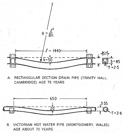
Fig. 19.2. The two examples of sagging lead pipes analysed in this case study. All dimensions are in mm.
TABLE 19.1 Conditions to whicb the lead pipes are exposed
|
Sample |
Range of (σs/μ) |
Range of T/TM |
Maximum |
|
External, drain, Cambridge, England, age: 75 years Hot water pipe, Montgomery, Wales, age: 70 years |
2.5 x 10- 5 to 1.0 x 10⁻⁴ 1 x 10⁻⁵ to 4 x 10⁻⁵ |
0.44 → 0 .5
0.46 → 0.53 |
~7 x 10-l 2
~6 x 10-12
|
Use of the deformation map for antimonial lead.
Maps for 0.5% antimonial lead (which typifies alloys used in England for pipes and roofing) are shown in Figs. 19.3 and 19.4.
They are computed from the data listed for lead in Table 4.1, with three
modifications. First the antimony lowers the melting point of lead to 595 K.
Second, the creep constants have been modified to fit the data of Hofmann
(1970, p. 237) [1] for antimonial lead at 30oC; to do so we
take n = 4.2 and A = 842, and retain Q = 109 kJ/mole as
before. Finally, the obstaclecontrolled glide parameters have been changed to
match the tensile strength of antimonial lead at 20oC and a strain
rate of 10-2/s, given by Hofmann (1970, p. 94); to do so we take ![]() .
.
The first map describes antimonial lead with a grain size of 50 µm, the grain size of the extruded pipes analysed here. On it are plotted, as shaded boxes, the ranges of stress and temperature to which the pipes are exposed. As a check on self-consistency, note that the strain rate contour of 10-12/s passes through both boxes: the map is in broad agreement with the observed mean strain rates (around 6 x 10-12 /s).
The second map shows the same lead, but with a grain size of 1 mm, roughly that found in cast lead pipe and sheet. Note that the predicted creep rates of the pipes are much smaller.
The first map (Fig.19.3) shows that the lead pipes deform by diffusional flow, of the kind controlled by grain boundary diffusion. This has certain consequences. The creep is linear-viscous, with little or no transient behaviour (this means that one can integrate over a history of stress and temperature). It is a very sensitive grain size—hence the advantage of cast sheet and pipes, a fact from which the Romans profited. An increase in grain size, to 1 mm (Fig. 19.4) slows the creep-rate by a factor of 103. Cast lead has an even larger grain size than this—it is typically 5 mm—and creeps not only more slowly, but—for the loading conditions of our pipes —by a different mechanism: suppressing diffusional flow causes the power-law creep field to expand until it includes both shaded boxes.
Though the creep of lead pipes is not a problem of pressing industrial importance, this case study has features which appear in reactor and turbine technology. The normalized stresses, homologous temperatures and strain-rates are similar to those involved in power-generating equipment (see the next two case studies). Diffusional creep, of the variety controlled by boundary diffusion, will frequently be the dominant mechanism of deformation in structures designed to last for 25 years at elevated temperatures. Yet it is often ignored in engineering design, which is normally based on an extrapolation of laboratory power-law creep data to the stresses encountered in the structure. The risk involved in doing this can be illustrated by the map of Fig. 19.3: if the power-law creep equation used to construct this map is extrapolated to predict the behaviour of the pipes, it gives the strain-rates slower by a factor of 103 than those observed.
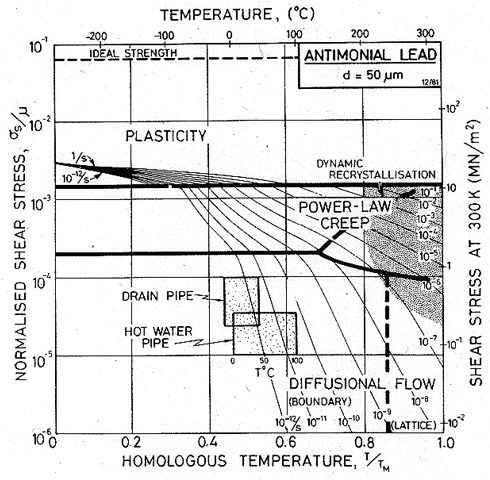
Fig. 19.3. A map for antimonial lead with a grain size of 50 µm, showing the conditions of operation of the pipes. Both deform by diffusional flow.
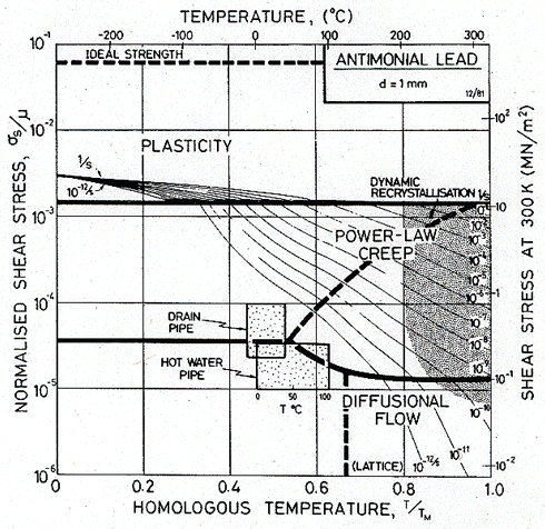
Fig. 19.4. Antimonial lead with a grain size of 1 mm. If the pipes had this grain size they would deform much more slowly than they do.
.
19.3 CASE STUDY: THE CREEP OF 316 STAINLESS STEEL IN A FAST NUCLEAR REACTOR
This case study illustrates the use of deformation maps to analyse components subjected to multiaxial stresses, and shows how they can help in selecting a constitutive law for design purposes. It further illustrates the use of transient (non-steady-state) maps to identify the dominant deformation mechanism, and the strains in the structure, when these are small.
The core of a fast reactor is quite small. To remove the heat, a coolant—either a liquid such as sodium, or a gas such as helium—must flow rapidly through it, and into a heat exchanger. In a liquid-metal-cooled reactor, the pressure differences needed to drive this flow, together with the weight of the structure and coolant itself, exert stresses on the structure supporting the core, on the pipework, and on the other components; in a gascooled reactor, the pressure differences are much smaller but the hydrostatic pressure needed to confine the gas imposes additional stresses.
Superimposed on these steady stresses are the thermal stresses which appear when the power output of the reactor changes. This is a problem of combined creep and low-cycle fatigue, and because they may not combine linearly, the rates of creep and the creep strains cannot be calculated safely from the equations of creep alone. The maps we present here should (if properly constructed) give a good description of the behaviour of reactor components under steady loading conditions, but they should not be used to give more than a qualitative picture of behaviour when loads change with time.
The temperature, and thus the efficiency of the reactor, is limited by the materials of which it is made. At present it appears likely that much of the internal structure of commercial fast reactors will be made of Type 316 stainless steel, a well-tried material for which long-term creep-rupture data are available. This choice limits, to a maximum of about 600°C, the temperature to which structural components of the reactor can be exposed. In the following hypothetical case study, we show how both steady-state and transient deformation maps may help a designer select the right constitutive law for his design calculations.
Fig. 19.5 shows, schematically and much simplified, a section through a hypothetical liquid-metal-cooled fast reactor. Liquid sodium contained in a pressure vessel is circulated through the core and heat-exchangers by pumps. We examine the creep of three components: the pressure vessel itself, the pipes leading from the pumps to the core, and the reactor skirt. We shall assume that all three are made of 316 stainless steel with a grain size of either 50 or 100 µm.
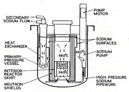
Fig. 19.5. Section through a hypothetical fast-breeder reactor.
The pressure vessel operates at the input temperature of the sodium coolant: 390 ± 30°C. Since all the components are suspended from the roof of the reactor, the loading of the vessel is merely that due to the weight of the sodium it contains, to buoyancy forces, and to the small pressure of helium gas which covers the sodium. The stresses in the vessel are highest in the side all near the bottom, about 8 m below the sodium surface, where the pressure due to the sodium alone is 0.074 MN/m2. To this we add the contribution of the overpressure pg of inert gas (0.007 MN/m2), giving a total pressure p of 0.08 MN/m2. These pressures, and the dimensions we assume below, broadly follow current designs. If, then, we take:
a = wall thickness of pressure vessel - 0.0125 m
r = radius of pressure vessel = 6 m
M = mass of sodium contained in the vessel including buoyancy forces from displaced sodium ~ 106 kg
the principal stresses in the vessel are:
![]() =
22.5 MN/m2(longitudinal)
=
22.5 MN/m2(longitudinal)
![]() = 38.4 MN/m2 (circumferential)
= 38.4 MN/m2 (circumferential)
σ3 = 0 (through wall thickness)
The maximum equivalent shear stress (eqn. (19.1)) is σs = 19.3 MN/m2. Near the top of the pressure vessel the equivalent shear stress in the wall is less (p is reduced to pg and σs to 12.5 MN/m2) and it is less in the hemispherical bottom because of its shape.
The sodium input pipes, too, operate at 390 + 30°C. The stresses in them are due mainly to the pressure difference between the sodium inside and outside a pipe, though there is a small additional contribution (which we shall neglect) at a bend in the pipe due to inertial forces set up by the rapidly flowing sodium. If we use the following hypothetical dimensions:
rp = pipe radius = 0.125 m
ap = pipe thickness = 0.005 m
pI = internal pressure = 0.83 MN/m2
pe = external pressure = 0.03 MN/m2
(corresponding
to a depth of 3 m of sodium)
then the principal stresses are:
 (axial)
 (circumferential)
and the equivalent shear stress, σs, is 10 MN/m2.
The interior reactor skirt is a cylinder, about 6 m in diameter, containing the core and associated structure. At least part of it is exposed to the hot sodium leaving the core at a temperature of 580 + 30°C. It is stressed because of the difference of 2 m in the sodium level inside and outside the skirt, this difference driving the flow through the heat exchangers; the consequent pressure difference is about 0.02 MN/m2. If, as before, we take hypothetical values for the dimensions:
![]() = skirt
radius = 3 m
= skirt
radius = 3 m
as = wall thickness of skirt = 0.005 m
we can calculate the stress state in the skirt. The circumferential stress σ2 is 11 MN/m2; and since it is supported from below, the longitudinal stress σ1 is negligible. The equivalent shear stress, σs, is 6.3 MN/m2.
This information, normalized by a (temperature-corrected) modulus, and by the melting temperature of iron (1810 K) is summarized in Table 19.2. We have allowed a + 20% variation in stress and a + 30°C variation in temperature about the values given in the text.
TABLE 19.2 Summary of conditions to whicb tbe reactor components are exposed
|
Component |
Range of (σs/μ) |
Maximum of T/TM |
|
Pressure vessel Sodium input pipes Reactor skirt |
2.3 x 10- 4→3.5 x 10- 4 1.2 x 10⁻⁴→1.8 x 10⁻⁴ 8.5 x 10⁻⁵→1.3 x 10⁻⁴ |
0.35→0.38 0.35→0.38 0.45→0.49 |
Deformation maps showing both the steady-state and transient flow of 316 stainless steel are described in Chapters 8 and 17; those relevant to this case study are shown in Figs. 19.6, 19.7 and 19.8. T he data used to construct them are given in Tables 8.1 and 17.1.
When strains are as small as this, the elastic and transient creep strains cannot be neglected. Though their construction requires more data, it makes sense to apply non-steady-state ("transient" maps, Chapter 17) to a problem such as this one. This is done in Figs. 19.7 and 19.8. They show maps for 316 stainless steel with a grain size of 100 µm. Transient maps, it will be remembered, show the strain reached in a given time, and the mechanism principally responsible for that strain. In a time 104 s (about 3 hours, Fig. 19.7) the strain in all three components is predominantly elastic, and of order 2 x 10⁻⁴.
As time elapses, the creep strains grow, so that after 30 years (109 s, Fig. 19.8) the creep strain in the reactor skirt is of order 1%; diffusional flow is the dominant mechanism. The other two components lie on the boundary between elastic deformation and diffusional flow, indicating that the contributions from the two are about equal (≈ 2 x 10⁻⁴).
These components are not exposed to a heavy neutron flux. If they were, a map incorporating radiation-induced, or radiation-enhanced, creep would be required. Such maps can be constructed (Ashby, 1971, unpublished), but are relevant only to the fuel, the fuel cans and the components immediately adjacent to the fuel pins.
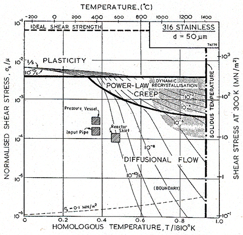
Fig. 19.6. A steady-state map for 316 stainless steel with a grain size of 50 µm, showing the operating conditions of the three reactor components, and the dominant steady-state flow mechanisms.
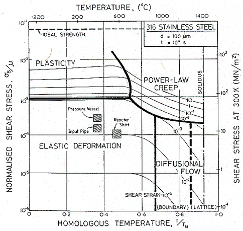
Fig. 19.7. A transient map for 316 stainless steel with a grain size of 100 µm, showing the strains which appear in 104 s. All three components deform elastically.
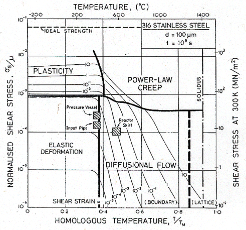
Fig. 19.8. A transient map like that of Fig. 19.7, but showing the strains which have accumulated in 109 s (roughly the life of the reactor). All three have suffered some creep strain; that in the reactor skirt may exceed 1%. Deformation is dominated by elasticity and diffusional flow.
Under the steady loads considered here, the distortion in the reactor components is elastic and by creep, the latter caused predominantly by diffusional flow. For much of the life of the reactor, the two contributions are of comparable magnitude. Transient contributions to diffusional flow and to power-law creep should not be neglected because their contribution is comparable with the elastic strain.
In certain reactor designs, the creep strain permitted in the life of the reactor—about 109 s—is limited to 1%. Fig. 19.8, which is constructed for this time span, shows that the pressure vessel and the sodium input pipe are well inside this limit. The inner reactor skirt, however, would exceed this permitted strain if our assumptions about dimensions and pressures are correct, even though the stresses in it are lower than for the other two components. Reducing the stress by a factor of two would not remedy this. An acceptable creep rate in the skirt could be obtained by selecting a steel with the same composition but a larger grain size: an increase to 200 µm, for instance, lowers the creep strain by a factor of 8.
A designer, concerned about the distortion of these reactor components under steady load and wishing to analyse them in more detail, should use a constitutive law which combines the elastic and creep deformation, including the transient contribution. The elastic distortion (in tensor notation) is:
|
|
(19.4) |
The dominant flow mechanism is Coble creep. Transient contributions to diffusional flow are discussed in Chapter 17; the relevant constitutive law is:
|
|
where
|
|
(19.5) |
and t is time. The data necessary to evaluate this equation are given in Table 17.1. If the designer is concerned with occasional overloads, he must first add to this the contribution from power-law creep and (if the overloads are large enough) from yielding; and second, take into account the possibility of fatigue failure and of interaction between creep and fatigue; these last are beyond the scope of this case study.
The case study leads to a further conclusion. Diffusional flow is poorly studied experimentally; the boundary-diffusion coefficients required to calculate its rate are not well documented, and the influence of alloying on it (Chapter 17) is only partly understood. There is a need for a major scientific study of diffusional flow in stainless steels.
19.4 CASE STUDY: CREEP OF A SUPERALLOY TURBINE BLADE
This case study is an example of the application of deformation maps to a component in which the stress and temperature vary with position. It illustrates the fact that strengthening methods are selective; a given method does not slow down all flow mechanisms equally.
Throughout the history of its development, the gas turbine has been limited in power and efficiency by the availability of materials that can withstand high stress at high temperatures. Where conditions are at their most extreme, in the first stage of the engine, nickel and cobalt-based superalloys are currently used because of their unique combination of high-temperature strength, adequate ductility and oxidation resistance. Typical of these is MAR–M200, an alloy based on nickel, strengthened by a solid solution of W and Co and by precipitates of Ni3(Ti,Al), and containing Cr to improve its resistance to attack by gases (Table 19.3).
TABLE 19.3 Nominal composition of MAR–M200 in wt.%
|
Al |
Ti |
W |
Cr |
Nb |
|
5.0 |
2.0 |
12.5 |
9.0 |
1.0 |
|
Co |
C |
B |
Zr |
Ni |
|
10.0 |
0.15 |
.015 |
.05 |
Balance |
This particular alloy, and descendants of it, used in the as-cast state—they cannot be rolled or forged—for turbine blades and vanes in commercial gas turbines. In aircraft use, start-up, shut-down, and frequent changes of power mean that steady state conditions very seldom apply. One could, however, envisage a steady state being reached in other applications: for example, in the use of such turbines for power generation, or in the use of MAR–M200 as a structure material in reactors or chemical plants. Here we shall use only steady-state maps for MAR–M200—insufficient data are available at present to construct transient maps for it. (An example of the use of transient maps for stainless steel is given in the case study preceding this one.)
When a turbine is running
at a steady speed, centrifugal forces subject each rotor blade to an axial
tension. If the blade has a constant crosssection, the tensile stress rises
linearly from zero at its tip to a maximum at its root. As an example, a rotor
of radius r of 0.3 m rotating at an angular velocity
![]() of 1000 radians/s
(11,000 r.p.m.) induces an axial stress (
of 1000 radians/s
(11,000 r.p.m.) induces an axial stress (![]() ) of order 10-3 µ,
where ρ is the
density of the alloy and l the distance from the tip. This stress and a
typical temperature profile, for a blade in an engine in use in the 1960s, are
shown in Fig. 19.9. The range of conditions is summarized in Table 19.4.
) of order 10-3 µ,
where ρ is the
density of the alloy and l the distance from the tip. This stress and a
typical temperature profile, for a blade in an engine in use in the 1960s, are
shown in Fig. 19.9. The range of conditions is summarized in Table 19.4.
These temperatures and stresses are averages over the cross-section of the blade, and are useful in giving a general idea of the mechanism of creep, and its approximate rate, under steady service conditions. When the power changes, the surface temperature of the blade rises or falls sharply, creating thermal stresses which are superimposed on those caused by centrifugal forces. They can be large, sometimes large enough to stress the skin of the blade above its yield stress. But the average stress in the blade remains in the range given by Table 19.4.
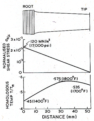
Fig. 19.9. The approximate distribution of axial stress and temperature along a turbine blade operating in the first sage of a typical turbine of the 1960s.
Table 19.4 Summary of average steady running conditions on blade
|
Range of temperature |
Range
of Stress |
Maximum acceptable strain rate |
|
0.45–0.58 TM |
0→2.3 x 10⁻³ |
~10-8 /s |
Figs. 19.10, 19.11 and 19.12 show deformation maps for pure nickel and for MAR-M200 of two grain sizes. The data on which they are based are listed in Tables 4.1 and 7.1, and discussed in Chapters 4 and 7.
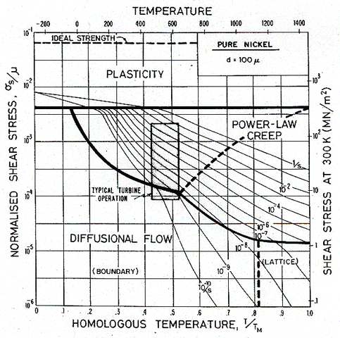
Fig. 19.10. A map for pure nickel with a grain size of 100 µm, showing the conditions of operation of the blade described by Fig. 19.9.
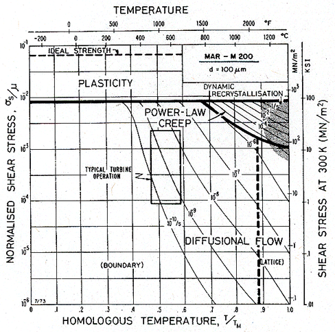
Fig. 19.11. A map for MAR–M200, with the same grain size as that for the nickel of Fig. 19.10 (100 µm). The shaded box shows the conditions of operation of the blade.
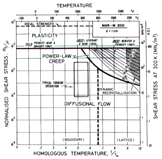
Fig. 19.12. A map for MAR–M200 with a large grain size (10 mm) approximating the creep behaviour of directionally solidified or single crystal blades. The shaded box shows the conditions of operation of the blade.
The steady running conditions given in Table 19.4 are plotted as a shaded box onto the maps. If made of pure nickel (Fig. 19.10) the blade would deform by power-law creep, at a totally unacceptable rate. By applying the strengthening methods used in MAR–M200 (Fig. 19.11) the rate of power-law creep has been reduced by a factor of 105, and the dominant mechanism of flow has changed— from power-law creep to diffusional flow. Further solution-strengthening or precipitation-hardening is now ineffective unless it slows this mechanism. A new strengthening method is needed: the obvious one is to increase the grain size. The result of doing this is shown in Fig. 19.12. This new strengthening method slows diffusional flow while leaving the other flow mechanisms unchanged. The power-law creep field expands, and the rate of creep of the turbine blade falls to a negligible level.
The point to remember is that plastic flow has contributions from several distinct mechanisms; the one that is dominant depends on the stress and temperature applied to the material. If one is suppressed, another will take its place. Strengthening methods are selective: a method that works well in one range of stress and temperature may be ineffective in another. A strengthening method should be regarded as a way of attacking a particular flow mechanism. Materials with good creep resistance combine several strengthening mechanisms; of this, MAR–M200 is a good example.
19.5 CASE STUDY: THE CREEP OF TUNGSTEN LAMP FILAMENTS
Deformation maps allow the performance of components to be compared, and suggest ways in which design might be changed to give better performance or longer life. In this case study we examine the performance of two tungsten lamp filaments.
The filament of a 25 or 40 Watt lamp is a singlecoiled wire of doped tungsten. Typical dimensions of a 40 Watt lamp are given in Fig. 19.13. LowWattage lamps like these burn at a temperature of 2250 to 2500°C, with an average life-time of about 1000 hours. (Higher-powered lamps run at higher temperatures: up to 2765°C for ordinary lamps and up to 3160°C for photo-flood bulbs—but their life is shorter: as short as 3 hours.)
A lamp may fail in one of several ways. Most fail because of evaporation from the filament surface, or the formation of a bubble or void within it, locally reduces the cross-section, producing a hot spot which accelerates evaporation and finally causes melting. The reason that most fail in this way, and not by creep, is that design against creep failure is adequate. What factors enter this design problem? To answer this question, we must first consider failure by creep.
The most probable mechanism of failure by creep is illustrated in Fig. 19.14. An undistorted coil is shown on the left; its dimensions for two sizes of lamp are listed in Table 19.5. Lamps normally burn with the filament horizontal. Then sag by torsional creep of the wire leads to overheating, and ultimately to shorting between turns as shown on the right. Suppose elements of wire on the upper side of the coil suffer a torsional creep strain resulting in a twist of θ per unit length; those Fig. 19.13. per unit length; those on the bottom suffer a similar twist in the opposite sense. Then the change of angle between the turns, φ, is approximately φ = 2Rθ where R is the coil radius. Contact occurs when:
|
φR = S – d |
where S is the turn spacing and d the wire diameter (Fig. 19.14). The shear strain at the surface of an element of the wire, γmax, is related to the twist per unit length by γmax = θd/2 The maximum permissible strain before shorting occurs is therefore:
|
|
If the lamp is to survive its rated lifetime, t, then the maximum permissible steady creep rate is:
|
|
Inserting data from Table 19.5 gives:
|
|
To allow a margin of safety against this sort of creep failure, the lamp should be designed so that the maximum strain-rate in the wire is less than 10-9/s,
The shear stress on the filament is calculated to a sufficient approximation as follows. Consider the equilibrium of a section of the coil of length l between the two supports, as shown in Fig. 19.15. If the mass per unit length of the coil is m0, then the length l between a pair of supports requires a force m0gl to support it. The upper side of each turn of the coil is then subjected to a torque T, where:
|
T~ 1/2 m0gl2 |
The coil sags as the wire deforms plastically under this torque. The mean shear stress in the wire, is defined by:
|
|
from which
|
|
The resulting normalized stress for the coils, together with the homologous temperatures and maximum strain-rates, are shown in Table 19.6. The stresses are low, but the temperatures are high— up to three-quarters of the melting point.
TABLE 19.5 Typical light bulb specifications
|
110 volt single-coiled lamps |
25 Watt |
40 Watt |
|
Burning temperature (°C) Design life (s) Turns/metre (m-1) Spacing of turns, S (mm) Wire diameter, d (mm) Coil diameter, 2R (mm) Total length of wire (mm) Total length of coil (mm) Total mass of coil (mg) Number of intermediate supports |
2250–2350 3.6 x 10⁶ 2.6 x 10⁴ 0.038 0.030 0.15 660 41 9.0 3 |
2400–2500 3.6 x 10⁶ 2.4 x 10⁴ 0.043 0.036 0.14 430 41 7.2 3 |
TABLE 19.6 Summary of conditions under which filaments operate
|
Power of lamp |
Range of σs/μ |
Range of T/TM |
Maximum
|
|
25 Watt 40 Watt |
0→1.0 x 10⁻⁴ 0→6.2 x 10⁻⁵ |
0.68→0.71 0.72→0.75 |
3.0 x 10⁻⁹ 3.6 x 10⁻⁹ |
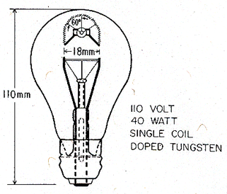
Fig. 19.13 Typical dimensions of a 40 Watt, 110 Volt, tungsten filament lamp. The filament is a simple coil of doped tungsten wire.
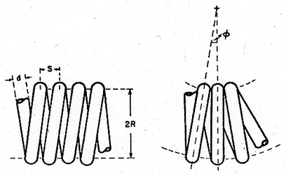
Fig. 19.14. The creep-failure of a tungsten filament. Torsional creep causes the windings to touch, causing overheating or shorting.
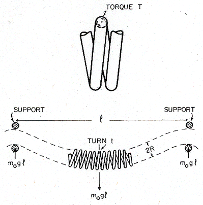
Fig. 19.15. The statics of a horizontal lamp filament.
Most filaments are made from doped tungsten: tungsten made from powder containing a little Al2O3, SiO2 and K2O (or mixed oxides of these three elements) which gives the wire added creep strength. Microstructurally, doping introduces a fine dispersion of bubbles which stabilizes an elongated, highly interlocked grain structure, of a sort which cannot be obtained in pure tungsten. Partly because these elongated grains impart good creep resistance (they make grain boundary sliding difficult) and partly because individual bubbles pin dislocations, doped tungsten has superior creep strength. The effect of doping is obvious when deformation maps for pure and doped tungsten are compared (Figs. 19.16 and 19.17).
The map for pure tungsten is constructed from the data listed in Table 5.1, and discussed in Chapter 5. That for doped tungsten is based on the measurements of creep in doped tungsten of Moon and Stickler (1970) [3]. Doping does not change the yield stress much; but it greatly reduces the rate of power-law creep, causing this field to shrink in size. We have fitted the map to Moon and Stickler's (1970) [3] measurements by altering the creep constants to n = 8.43 and A = 8.4 x 10¹⁴, leaving all the other parameters unchanged.
Although the grains in doped tungsten are small in two dimensions, they are large in the third, being about 1 mm long in the direction of the wire axis. For diffusional flow, it is this long dimension which counts, so the map is constructed for grains of this size. The map for pure tungsten, too, is for 1 mm grains, partly to make comparison easy, and partly because pure tungsten readily recrystallizes to give large grains if heated above about 1600°C.
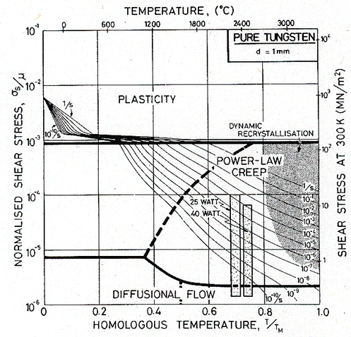
Fig. 19.16. Pure tungsten with a large grain size (1mm). The shaded boxes show the conditions of operation of the two lamp filaments.
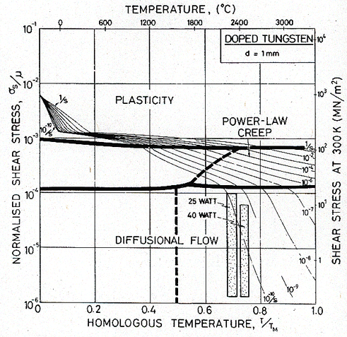
Fig. 19.17. Doped tungsten. In wire made of doped tungsten the grains are elongated; their long dimension can be as great as 1 mm. For that reason a grain size of 1 mm has been used here. The shaded boxes show the conditions of operation of the two lamps.
The information summarized in Table 19.6 is shown on the maps as shaded boxes, each box defined by the range of temperature and stress to which a filament is subjected. Suppose, first, that the filaments were made from pure, large-grained tungsten (Fig. 19.16). The maximum creep rate (top of the box) would be about 10-4/s: the filament would fail by creep in about 30 s. The mechanism leading to this rate is power-law creep, so (unlike the examples of the lead pipe and turbine blade) increasing the grain size, if that were possible, would do no good. We require a strengthening mechanism which suppresses power-law creep without accelerating diffusional flow.
Doping successfully does this (Fig. 19.17). The boxes show that the maximum creep rate is now about 4 x 10-l0/s, comfortably below the limit required for adequate life. Further, the dominant creep mechanism may have been changed by doping: the tops of the boxes now lie close to the boundary between power-law creep and diffusional flow.
Fig. 19.17 can be used as a guide for change in filament design. If the temperature is raised, the maximum stress on the filament must be reduced—by providing more intermediate supports, for instance—so that the top of the box remains below the contour of 10-9/s. If it does not, failure by creep will occur in less than 1000 hours, and the life of the lamp will be reduced.
19.6 CASE STUDY: METAL-FORMING AND SHAPING
The various regimes of metal-forming and machining can conveniently be presented on a deformation map. The result puts the regimes of metal-forming into perspective, shows the deformation mechanisms underlying each, and gives a rough idea of the way in which the forming forces change if the rate of the process, or the temperature at which it is performed, are altered.
Strain rates between 10-12/s and 105/s—a range of 17 decades—are encountered in engineering practice. Those associated with metal-forming and shaping lie at the upper end of this range, between 0.1/s for slow extrusion and 105/s for fast machining. The temperatures, too, cover a wide range. Cold working is carried out at room temperature. Warm working involves temperatures in the creep regime but below those at which recrystallization will occur. Hot working requires temperatures above the recrystallization temperature. Extrusion involves yet higher temperatures.
The plastic strains involved in metal-working are often large—of order 1; by comparison the elastic strains are negligible, and the material can be thought of as reaching its steady-state flow stress. For this reason, we plot the regimes of metalworking onto a steady-state map (we have used copper as an example) based on data for the ultimate tensile strength.
In the following sections, the characteristics of a number of metal-forming operations are discussed. The data are summarized in Table 19.7.
TABLE 19.7 The conditions of metal-forming
|
|
True strain range |
Velocity range (m/s) |
Strain rate range (s-1) |
Temperature range |
Reference |
|
Cold working |
0.1→0.5 |
0.1→100 |
1→2 x 10³ |
Room temperature (slight adiabatic heating) |
|
|
|
|
|
|
|
|
|
Wire drawing |
0.05→0.5 |
0.1→100 |
1→2 x 10⁴ |
Room temperature to 0.3 TM (adiabatic heating) |
|
|
|
|
|
|
|
|
|
Explosive forming |
0.05→0.2 |
10→100 |
10→103 |
Room temperature |
Bitans and Whitton |
|
|
|
|
|
|
|
|
Machining |
~ 1 |
0.1→100 |
102→105 |
Room temperature to 0.4 TM (adiabatic heating) |
Boothroyd (1965) [5] |
|
|
|
|
|
|
|
|
Warm working |
0.1→0.5 |
0.1→30 |
1→103 |
0.35→0.5 TM |
|
|
|
|
|
|
|
|
|
Hot working |
0.1→0.5 |
0.1→30 |
1→103 |
0.55→0.85 TM |
Higgins (1970) [6] |
|
|
|
|
|
|
|
|
Extrusion |
~ 1 |
0.1→1 |
0.1→102 |
0.7→0.95 TM |
Feltham (1956) [7] |
Rolling and forging are among the simplest of forming operations (Fig. 19.18). They can be performed cold at room temperature (though adiabatic and frictional heating may raise the temperature a little); warm, in the temperature range 0.3 to 0.5 TM, too low for recrystallization, but high enough to reduce the forming forces; or hot, in the temperature range 0.6 to 0.9 TM, the regime of dynamic recrystallization, when the forming forces are lower still.
Cold working gives greater precision, and much better surface finish than hot or warm forming. The velocities of rolling or forging can be high (as high as 100 m/s) but the reductions are generally small, giving strain-rates in the range of 0.1 to 103/s (Table 19.7).
Hot working allows larger reductions and lower roll or forge pressures. Typical of hot working (Higgins, 1970) [6] is the rolling of steel ingots. They are preheated to between 800 and 1250°C (0.65–0.85 TM) and run through rolls which impose a strain of 0.1 to 0.5 per pass, at velocities of up to 1 m/s. Forging is carried out at comparable temperatures and speeds. For normal billet dimensions, the strain-rates are between 1 and 103/s. Table 19.8 summarizes forging and extrusion temperatures for copper, aluminium and lead-based alloys, and for steels. It illustrates that hot rolling and forging are typically carried out at 0.6–0.8 TM while extrusion requires higher temperatures: 0.7–0.9 TM.
Although the forces are higher during warm working, problems of oxidation and scaling are reduced, and the texture introduced by the forming operation is retained. Velocities and strain-rates are listed in Table 19.7; they are much the same as those for hot working.
Almost all the work done during a forming operation appears as heat. The temperature rise in the workpiece depends on many factors (Johnson and Mellor, 1973 [8]), but it can be large: sufficient to cause a temperature rise of 0.3 TM.
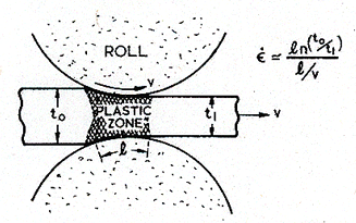
Fig. 19.18. Rolling. The average strain-rate depends on the reduction in section t0/t1, on the length of contact with the rolls, l, and the rolling velocity υ. It is given approximately by the expression on the figure.
Fig. 19.19 illustrates a typical drawing operation. The wire or sheet is drawn through a lubricated die at speeds of 0.1 to 100 m/s. A strain of (typically) 0.05 to 0.5 is imposed as the metal passes through the die, which is in contact with the wire over a distance of 1–10 mm, giving strain rates which can exceed 104 /s—rather higher than those involved in cold rolling.
Wire is usually drawn cold (though adiabatic and frictional heating can raise the temperature to 0.3 TM). Refractory metals are the exception: to avoid the ductile-to-brittle transition, which can lie above room temperature, materials such as tungsten are preheated to around 600°C (0.25 TM) for wire drawing.
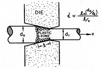
Fig. 19.19. Wire drawing. The average strain-rate depends on the reduction in diameter, d1/d0, the contact length l and the velocity υ.
Explosive forming is one of the more recent developments in metal-working. It lends itself to the making of one, or a few components—often large (such as the end caps for large pressure vessels) or of difficult materials (high-strength steels, for example). Typically an explosive charge is detonated, or an electrical discharge triggered, below the surface of a liquid which acts as a transfer medium (Fig. 19.20). The shock wave presses the material into a former, at a velocity υ, which depends on the transfer of energy to the workpiece; it is typically 50 m/s. The time taken for it to do this determines the strain rate, which for "stand off" charges like that shown in Fig. 19.20, is relatively small: between 10 and 102 /s. The resulting temperature rise is slight, perhaps 20°C.
Sometimes the charge is applied to the surface of the workpiece itself. The strain-rates then depend on the rate at which the explosive burns, and can be higher: up to 104 /s (Bitans and Whitton, 1972) [4].
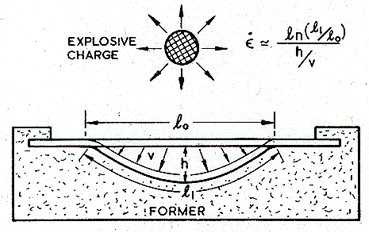
Fig.19.20. Explosive forming. The average strain-rate is the strain ln (l1/l0), divided by the time h/υ required to achieve it. These strain rates are not as large as those often encountered in machining or wire drawing.
The highest strain-rates are encountered during machining. Fig. 19.21 illustrates the process, which typifies turning, drilling, milling or shaping. The workpiece and the cutting tool move with a relative velocity υ, removing a chip of width a. The fundamental process is one of shear. In forming the chip, the material (if it does not fracture) suffers a shear of order 1 in traversing a distance of order a. The strain-rate is then:
|
|
It can be very large: surface velocities during machining range from 0.1 to 100 m/s and the chip thickness is typically of order 1 mm, giving strainrates in the range 102 to 105 /s.
At these high strain-rates, deformation is purely adiabatic (Chapter 17, Section 17.2). Then the temperature rise is large—as much as 0.4 TM—and localization of flow, leading to serrated machining chips and a poor surface finish, can result.
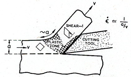
Fig. 19.21. Machining. The highest strain-rates are encountered during machining.
Working temperatures are highest in extrusion (Fig. 19.22). Typically, a ram forces material to flow through a shaped die, at velocities of between 0.1 and 1 m/s. The strains involved are large—of order 1 giving strain-rates of up to 102 /s. The temperatures (Table 19.8) are in the range of 0.7 to 0.95 TM.
TABLE 19.8 Temperature of hot working and extrusion
|
Material |
Forging or hot rolling |
Extrusion |
|
Al alloys |
320→450°C (0.65→0.8 TM) |
450→500°C (0.7→0.85 TM) |
|
Cu alloys |
450→900°C (0.55→0.85 TM) |
650→1050°C (0.7→0.95 TM) |
|
Pb alloys |
100→200°C (0.6→0.8 TM) |
200→250°C (0.8→0.9 TM) |
|
Steels |
800→1250°C (0.6→0.85 TM) |
1100→1300°C (0.75→0.85 TM) |
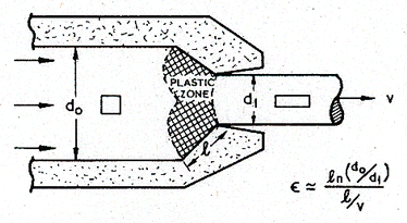
Fig. 19.22. Extrusion. The highest homologous temperatures are encountered during extrusion.
|
The use of deformation maps to display metal-forming conditions |
Fig. 19.23 shows the regime of each forming operation (Table 19.7) plotted onto a map for copper. This map is based on the data listed and discussed in Chapter 4, and includes power-law breakdown. The low temperature side of the map uses data for the (true) tensile strength since this approximates most closely the resistance to plastic flow reached in the large strains of metal-forming .
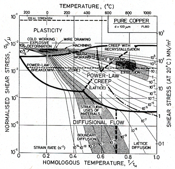
Fig. 19.23. A steady-state map for copper, based on data for the tensile strength and steady-state creep, and including power-law breakdown. The regimes of metal forming are shown, and are contrasted with the regime of the engineering application of alloys.
The figure illustrates in a compact way the regimes of stress, strain rate and homologous temperature associated with each operation. Although the map is for copper, it broadly describes the forming of any f.c.c. metal if the normalized axes σs/μ and T/TM are used. The data for Table 19.7 can be replotted onto other maps in this book to illustrate forming of b.c.c. or h.c.p. metals, or their alloys.
The effect of changed working conditions on forming forces can be seen from the diagram. In going from cold working to hot working at the same strain-rate, the shear strength of the material falls by a factor of more than 4. If the coefficient of friction remains constant, then the forming forces and work of forming fall by the same factor. Increasing the rate of forming does not change the forces required for cold work much, but can have a large effect in hot work (a factor of 100 in rate can double the forces).
As well as the regimes of metal-working, the figure shows the regime in which engineering alloys are generally used. Most structures are designed to last for some years; a strain-rate in excess of 1% per 1000 hours (3 x 10⁻⁸/s) would certainly be considered excessive. Structures such as nuclear reactors are designed to much more rigid specifications, sometimes requiring as little as 1% strain in 20 years (10-ll/s). The regime bounded by these limits is shown as a shaded band on the figure, which includes contours of strain-rate down to 10-l4/s, a regime of interest to geologists and geophysicists, and to those concerned with the safe storage of nuclear waste.
This case study illustrates why an ability to extrapolate laboratory data is so important. Metal-forming operations involve strain-rates which are higher than those usually used in laboratory tests. Most structural operations involve strain-rates which are lower. The great body of careful laboratory data, not only for copper but for other metals and alloys, too, lies in the gap between the metalworking and the structural uses. To be useful in understanding the processes described here, it must be extrapolated, often through many decades of strain-rate.
19.7 CASE STUDY: CREEP IN THE SOUTH POLAR ICE CAP
This is a simple, geophysical application of the maps. Phenomena such as glacial flow, the creep deformation of rocks, or the formation of salt domes might be treated in a similar way. It illustrates how the maps can be used to identify deformation mechanisms, even when the stress and temperature vary with position. A proper identification is, of course, essential if the phenomenon is to be modelled.
Of all the crystalline materials to be found on the earth's surface in a more or less pure form, ice is by far the commonest. The South Polar Ice Cap alone contains some 1015 cubic metres of pure ice; a large glacier might contain 1011 cubic metres. Acted on by gravity, much of it is creeping.
Studies are at present in progress with the ultimate goal of solving the coupled heat and mass-flow equations which would describe completely the accumulation, flow and attrition of ice bodies such as the South Polar Ice Cap (e.g. Budd et al., 1971 [9]). The mechanical movement is complicated: part of the surface displacement (which can be measured) is due to creep within the ice; part may be due to sliding at the surface where the ice contacts bedrock. To model the creep contribution, the proper constitutive law must be chosen. This choice is the topic of this case study.
The surface temperature in Antarctica varies with the seasons, reaching a minimum of about –58°C. A few tens of metres below the surface, the temperature ceases to fluctuate with the seasons, and rises slowly to 0°C at bedrock where the geothermal heat flux is thought to be sufficient to maintain a film of water. The elevation of the ice surface has a maximum value of 4000 m near the centre of the continent, where the rate of snow accumulation is highest; from this high point, the ice sheet slopes gently outwards for 1000 km or more, before falling steeply to the open sea. The ice sheet overlies bedrock. Where radar-echo surveying techniques have been applied, the shape of the underlying terrain is known to be irregular, with ridges up to 2000 m high separated by broad, deep valleys. This complicates the flow of the sheet, which is channelled by these valleys, at least near its edges.
Reduced to its simplest, the stress analysis for gravity-driven flow in the ice sheet is shown in Fig. 19.24. The gradient in surface height generates a shear stress which increases linearly with depth, and has the magnitude:
|
σs = ρgh sin α |
where ρ is the density of the ice, g the acceleration due to gravity, h the distance below the surface and α the surface gradient. The gradient at Byrd Station (α = 2.5 x 10⁻³) is broadly typical of the Antarctic plateau; and at this point, the temperature profile with depth has been measured by making borings. These measurements, and the associated stresses, are shown in Fig. 19.25. The pressure, even under 3 km of ice, is too small to change the mechanical properties significantly—unlike the situation described in the next case study.
Ice is remarkably well studied in the temperature range of interest here: –40°C to 0°C. The data and maps are described in Chapter 16. The grain size in Antarctic polar ice is known (Gow et al., 1968 [10]): cores drilled at Byrd Station show that near the surface, where the porosity is considerable, the grains are about 1 mm in diameter; deeper; (below 200 m) where the porosity has almost vanished, it increases to about 10 mm. This is the grain size we need, since almost all the deformation occurs below this depth.
At these greater depths the ice has a texture or fabric. (This may be evidence of flow by a mechanism involving dislocation motion, and supports the conclusion we reach here, that power-law creep is the dominant deformation mechanism; diffusional flow is not expected to produce a texture, and may even destroy one). Given sufficient data, one could produce deformation maps for plastically anisotropic materials, though the method is clumsy and we shall not attempt it: it requires a new map for each direction of shear and each level of texture. Instead, we make the considerable approximation of treating the ice as isotropic.
The stress/temperature profile of the ice cap at Byrd Station, plotted onto a map for ice with a grain size of 10 mm, is shown in Fig. 19.26. At bedrock, both the stress and temperature are at their highest. The creep strain rate is highest here—about 10-9 /s according to the map—and falls as shown with decreasing depth. The important part of the stress temperature profile lies in the power-law creep field: this is the dominant mechanism of plasticity. But one must be careful: if (because, say, of impurities or included dust particles) the ice elsewhere had a smaller grain size—0.1 mm for example—then the entire Antarctic ice cap would deform by diffusional flow (Figs. 16.3 and 16.6).
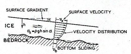
Fig. 19.24. The shear stress in an ice body with a surface gradient α of σs. This leads to the velocity distribution shown. There may be a velocity discontinuity due to sliding at bedrock.
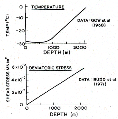
Fig. 19.25. The temperature and stress distribution in the ice sheet at Byrd Station, where the total depth of ice is 2.2 km.
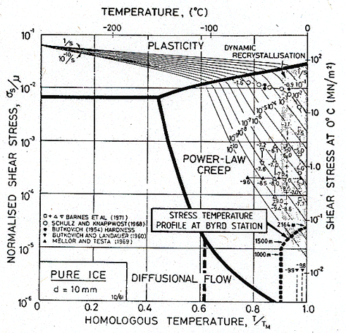
Fig. 19.26. A map for ice with a grain size of 10 mm. The stress-temperature profile of the ice at Byrd Station is plotted onto it. Most of the ice body deforms by power-law creep.
19.8 CASE STUDY: THE RHEOLOGY OF THE UPPER MANTLE
This geophysical application of deformation maps illustrates how large pressures influence the mechanisms of plastic flow.
The continents float on, and drift in, a thick shell of matter known as the upper mantle. Acoustic and petrologic measurements suggest that the most abundant phase in this shell is olivine, a silicate with the approximate composition (Mg0.9 Fe0.1)2Si04. Samples ejected on the earth's surface show pale green, transparent grains with a size of about 5 mm. If, as is thought, olivine is the connected phase in the mantle (though it contains other phases as well), then to a first approximation flow in the upper mantle might be treated as flow in a layer of pure olivine.
There is considerable interest in modelling the process by which the continents slowly drift, moving about 1 cm a year. As with the ice-flow problem of the last case study, the stresses and temperatures vary with position, so a complete analysis requires the simultaneous solution of the differential equations of heat and mass-flow. But it is more difficult than the ice problem because the material properties are less well documented, and because the drift itself must be driven by convection in the mantle—a phenomenon hard to model. Any attempt to do so requires a flow-law describing the mechanical behaviour of olivine under the conditions found in the mantle. A deformation map for olivine gives insight into the proper choice for this law (Stocker and Ashby, 1973 [11]; Ashby and Verrall, 1977 [12]), and allows the effects of pressure to be investigated.
|
Pressure, temperature, stress and strain-rate in the upper mantle |
Values of the material properties and microstructural variables in the upper mantle are uncertain, and, at best, can only be assigned upper and lower limits. The one exception is the pressure: the rock densities and the gravitational constants needed to calculate it as a function of depth are known. To a sufficient approximation, it is given by:
|
p = 105 + 3.2 x 10⁴ ∆ |
(19.6) |
where p is the pressure in N/m2 and ∆ is the depth in metres. (This identifies the pressure as that due to the atmosphere plus a height ∆ of rock of average density 3.25 x 10³ kg/m3.)
The temperature distribution is less certain. An acceptable approximation is arrived at by combining information about the temperature gradient at the earth's surface (about 12 K/km) and the melting temperature of certain phases in the mantle, with seismic data indicating the depths at which phase changes in the upper mantle and lower mantle occur (indicating a temperature of 1850 K at a depth of 500 km). The result is the temperature profile, or geotherm:
|
T = 300 + 1580 (1 – exp – (7.6 x 10⁻⁶∆)) |
(19.7) |
when T is the temperature (K).
The magnitude of the shear stress causing flow in the mantle can be inferred from the external gravitational potential, and from stress drops during earthquakes (see, for example, McKenzie, 1968 [13]). Stresses between 0.1 and 50 MN/m2 encompass all values derived from these two methods although a narrower range—0.1 to 20 MN/m2—is more likely. The local stresses, of course, may be greater than this; but while they are important in the triggering of earthquakes, they can have little effect on flow on a global scale.
Finally, a limit can be placed on the strain-rates involved. Continents are known to have drifted distances of the order of 5000 km in times of order 2 x l08 years. If the shear involved occurs in a layer of the upper mantle 200 km or less in thickness (as is generally supposed) then the strain-rates must be greater than 10-l5 /s; and direct measurement of current rates of drift indicate that they are certainly less than 10-l2 /s.
The grain size in the upper mantle is not known. Where olivine is found on the earth's surface, the grains within it have a size between 0.1 and 10 mm, though the process by which it reached the surface may have altered its structure.
|
Deformation maps for olivine, including the effects of pressure |
The mechanical properties of olivine at atmospheric pressure are reviewed in Chapter 15. In the upper mantle the pressure is large enough to change most of them seriously: the lattice is compressed, increasing the moduli and the low-temperature strength; and (most important) the activation energies for diffusion and for creep are increased, reducing their rates. These changes are discussed in Chapter 17. To tackle the present problem, they must be included.
The Burger's vector, molecular volume, and moduli and the strength at 0 K are adequately described by:
|
|
(19.8) |
Here, K is the bulk modulus and p the pressure, and the subscript "0" means the value at room temperature and pressure. The influence of pressure on diffusion and creep is included by making the activation energy depend linearly on pressure:
|
|
(19.9) |
where V* is the activation volume for diffusion. The diffusion coefficients depend strongly on these activation volumes, the values of which are not well established. Because of this, the maps for olivine at pressures other than atmospheric may be seriously in error.
The data listed in Table 19.10 are the best we are able to deduce from the information at present available. Maps computed from these and the parameters given in Chapter 15 are shown in Figs. 19.27 and 19.28. The first is for atmospheric pressure, the second is for a pressure of 0.1 K0.
TABLE 19.9 summary of limits on conditions in the upper mantle
|
Material |
Range of σs/μ |
Range of T/TM |
Range of
|
Range of grain size (mm) |
|
Impure olivine |
10-6→6 x 10⁻⁴ |
0.5→9.5 |
10-15→10-12 |
0.1→10 |
Guidance in identifying the dominant flow mechanism in the upper mantle is obtained by plotting the range of stress, temperature and strain rate given in Table 19.9 onto deformation maps for olivine. The reader will quickly convince himself that olivine, at atmospheric pressure, and with a grain-size of 1 mm or larger (Figs. 15.1 and 15.3), will flow, under these conditions, by power-law creep. Pressure displaces the contours and field boundaries in such a way as to make this even more certain, as will be illustrated below.
The smallest possible grain size of olivine in the mantle is, perhaps, 0.1 mm. Fig. 19.27 shows a map for this material at atmospheric pressure. The conditions of Table 19.9 are shown on it as a shaded band: they lie entirely in the field of diffusional flow. This, however, is misleading: the pressure in the mantle is far higher than that of the atmosphere. Fig. 19.28 shows a map for olivine of the same grain size, but at a pressure p = 0.1 K0, corresponding to a depth of 380 km. The pressure has raised the yield strength and reduced (by a factor of about 1000) the rate of creep. The shaded area now straddles two fields: power-law creep and diffusional flow.
We conclude that, if the grain size in the upper mantle is 1 mm or larger, the dominant flow mechanism is power-law creep. But if the grain size is 0.1 mm or smaller, an important contribution is made also by diffusional flow. We cannot at present be sure that some new mechanism, such as fluid-phase transport (Stocker and Ashby, 1973[11]; Ashby and Verrall, 1977 [14]) does not contribute also. But even allowing for the wide range of uncertainty in the imposed conditions and in the material properties—the presumption of power-law creep seems the most reasonable one.
TABLE19.10 Additional data for olivine
|
Bulk modulus Pressure dependence Pressure dependence Temperature dependence
Activation volume Activation volume |
K dμ/dp dK/dp
|
(MN/m2)
(m3/mole) (m3/mole) |
1.27 x 10⁵ 1.8 5.1 0.26
6.9 x 10⁻⁶ 6.9 x 10⁻⁶ |
(a) (b) (b) (a)
(c) |
|
(a) Huntington (1958) [15]. (b) Graham and Barsch (1969) [16]; Kamazama and Anderson (1969) [17]. (c) Ashby and Verrall (1977) [14]. |
||||
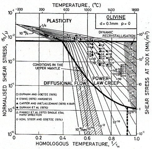
Fig. 19.27. A map for olivine with a grain size of 0.1 mm at atmospheric pressure.
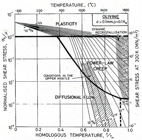
Fig. 19.28. A map for olivine based on the same data as Fig. 19.27, but for a pressure, p, of 0.1 K0, (1.3 ´ 104 MN/m2), corresponding to a depth of 380 km. The flow strength at low temperatures has increased by a factor of 1.5, and the creep-rates have decreased by a factor of about 103.


