|
 |
|
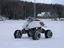
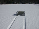
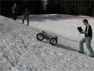
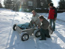
The robot, fully assembled and running at long last, driving in front of thayer on a sunny afternoon. Alex sends driving commands via radio and monitors the robot's health and progress. The power system has not quite evolved to the point where it can handle multiple panels' input, but does operate well enough with just one.
|
|
|
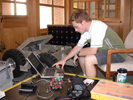
With a project even of this relatively modest size, there are 1,001 little problems that need to be ironed out and fixed right at the last moment. Here, Alex works on tracking down #742.
|
|
|
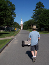
A nice shot of us driving the robot via radio control, sans solar panel box, towards Dartmouth's Baker Library along Tuck Drive one fine afternoon during the final testing before Greenland.
|
|
|
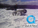
In this very latest action footage, (mascoma_driving.mov, 8.2 MB) was taken out on Lake Mascoma. With the larger, 20" tires, we drove the robot over the most rugged features we could find on the otherwise flat lake surface. While the snow was much softer here than it would be in Antarctica, the size of the features is comparable to a rough expanse of sastrugi. As one can see from this footage, the robot can tackle this rough stuff without slowing down.
|
|
|
Our testing on Lake Mascoma coincided with a week of field testing being done by Carnegie Mellon's Field Robotics Center. They had brought the Nomad rover here to practice autonomous navigation on snow and ice, in preparation for more ambitious missions. Although the picture does not show it very well, Nomad is a tremendous piece of work, nearly the size of a Jeep. Our own modest robot would not even come up to Nomad's knees.
|
|
|
In a rugged snowfield strewn with the tracks the robot made as we drove it back and forth across obstacles, the Cool Robot makes it way up yet another, with Dr. Jim Lever observing in the background.
|
|
|
At one point, while driving the robot manually through a turn via radio control, we lost communications. While we were trying to sort it out, the robot continued to follow the last command we sent to it, which was to keep turning. As a result, the robot kept going around in circles. The relatively small amount of drift in its path as this happened is a testament to the excellent alignment of the powertrain.
|
|
|
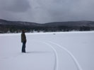
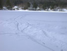
The Cool Robot's navigation system is very low bandwidth, meaning that it makes its corrections quite slowly (in the middle of Antarctica, who needs to turn on a dime?). The result, while guiding itself from one waypoint to the next is a long and winding path seen here.
|
|
|
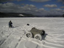
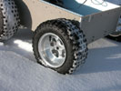
Our robot making tracks through several inches of soft, powdery snow on top of 18" of ice on Lake Mascoma. The larger, 20" tires make a huge difference in adding ground clearance, and the tread pattern is a little better for this soft stuff.
|
|
|
The large tires, wide wheelbase, and low center of gravity allow the robot to pitch and roll as it encounters changes in terrain and contour. Here, one can see the track of the robot as it went over a relatively steep drop, no unlike the leeward edge of a snow berm considerably larger than a typicalsastrugi.
|
|
|
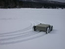
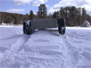
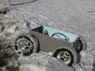
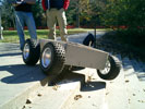
Even with the larger 20" tires, the robot can still run into an obstacle which will cause it to become "high centered." In this case, the robot is supported on its belly, meaning that the tires have very little grip with the snow. This has happened only a very few times since adding the new tires, and is usually compounded by loose snow. We are working on ways of detecting and resolving these occurrences autonomously or via teleoperation.
|
|
|
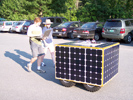
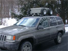
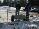
The robot is still light enough (37 kg, which is about half of its final projected weight) that two people can lift it on top of a car and lash it down for field testing.
|
|
|
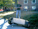
On packed snow, we've found that the Cool Robot's mobility is all that we'd hoped for and more. Without hardly a flinch, the robot is able to drive up a 30-40 degree incline at full speed. The powertrain is strong enough that, if it had the traction for it, the robot could probably climb a vertical wall!
|
|
|
Try as we might to design a robot with great mobility, we cannot foresee all possible terrains and paths. In this case, we managed to become high-centered on a pile of snow similar to a large sastrugi. Going forward was no good, just spinning wheels, but we can always back up. Thankfully, it is pretty obvious, in terms of motor speeds and currents, so we will be able to detect and correct this situation autonomously.
|
|
|
Putting the robot through its paces consists largely of trying to drive it over as many different obstacles and terrains as possible. This imitation sastrugiprovides an interesting challenge by combining a climb with very weak snow.
|
|
|
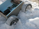
When we lose traction, it is not from a failing of the tires exactly, but from the fact that the snow fills in the tread, and then the only traction comes from snow-on-snow, which is pretty weak. When this happens, spinning the wheels only succeeds in digging further in.
|
|
|
Before the robot goes trundling off on its own, it requires some setting up. In the foreground is Toni doing just that. Behind him is Max, and to the right is Taro, who are working on a parallel project to develop a rover equipped with a ground-penetrating radar unit that would search for crevasses ahead of a traverse team.
|
|
|
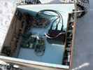
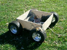
Compared to an indoor picture further down, we've managed to organize and expand the wiring a bit. Also, we have started to line the interior with 1-inch blueboard insulation, a job that will be ongoing as we determine how much heat we generate, and how cold the interior gets. Adding an insulated lid to the chassis (which is currently sporting its convertible racecar look) will go a long way toward that end.
|
|

|
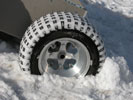
A closeup of the impression our current, 16-inch tires make in soft snow. The dot just left of center is a penny, provided for scale. So long as the tread does not get clogged with snow, the tread pattern is extremely effective for providing traction.
|
|
|
While we expect the snow conditions of the Antarctic to be firmer than this, this is an example of some of the snow conditions we encounter here in Hanover, NH. The compaction of the snow you see makes a noticeable increase to the rolling resistance (and hence, energy requirements) of the robot.
|
|
|
Although the Cool Robot is not quite finished, and a little rough around the edges, it strikes an impressive pose with Götz and Jim.
|
|
|
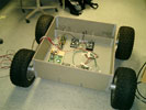
After about a year's worth of design, small-scale testing, procurement, and fabrication, our rolling chassis is complete. In this picture, one can see the four motor controllers, the housekeeping power supply and microcontroller electronics. Hidden behind the honeycomb walls are the four drivetrain assemblies. Absent from this picture are the batteries, which will form the core of the final power system and will be used to power the robot during initial testing.
|
|
|
Because we simply couldn't contain ourselves, we quickly took our prototype outside (the first time it's seen the light of day) to see it operate. In the back right corner is the battery bank (three Ultralife UBI-2590 12 A-hr Li-Ion batteries). The tether snaking off to the right provides control via a laptop computer. The popsicle stick at left is there so that we know which end is "front" when driving.
|
|

|
This clip (driving_on_grass.avi, 2.6 MB) shows that our robot, can travel with ease at about walking speed. Here the robot is being guided and controlled by a human operator (Goetz Dietrich) via a laptop computer. The self-navigation via GPS is still in development.
|
|
|
|
This clip (turn_on_grass.avi, 644 kB) demonstrates how we use skid-steering on the robot to turn. We'll be doing it on snow, but here we do it on the front lawn. It does not turn on a dime, because the coupling of one motor-gearhead pair is a little weak at the moment.
|
|
|
|
This clip (stairs_straight_on.avi, 3.6 MB) shows how the incomplete robot is able to climb a set of stairs straight-on under its own power. The control is provided via tether to a laptop. In this testing scenario, the usefulness of upgrading to 20" tires (these are 16") is evident.
|
|
|
Here, we give the rolling chassis a real workout by getting it to drive down (and then up again) a flight of stairs. Like the clip below, the robot is taking the stairs at an angle. Like with the picture above, on can see that, with the weight unequally distributed amongst the wheels, the chassis flexes a bit. In one sense, this is beneficial, as the robot has no suspension system.
|
|
|
|
This clip (stairs_diagonal.avi, 2.6 MB) shows the robot's ability (even at this incomplete stage, where construction is not finished) to traverse some rugged terrain by climbing a set of stairs diagonally. The robot is under human control via a tether to a laptop, but is completely self-powered.
|
|
|
Another picture of the rolling chassis at work, this time transitioning from loose soil on an incline up to a concrete sidewalk. In order to do so, it has to climb up over a three inch step. No big deal. One can see that, although quite stiff, the chassis can still flex when it doesn't have all four wheels on the ground. This will improve when we fashion the chassis lid and solar panel box.
|
|
|
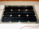
In the process of developing this fabrication method, we built two 12-cell panels. Testing of these panels reveal that they are >18% efficient and can produce about 30-35 W in full sunlight. The finished robot will have 272 cells on it and be capable of producing 250-400 W.
|
|
|
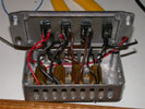
To test our smaller, 12-cell panels, we wanted to be able to fully characterize the I-V curve. To do that, we would connect the panel to this load box, which contains a number of low-value, 25W power resistors. The rayed lines on the I-V curve above represent lines of constant resistance.
|
|
|
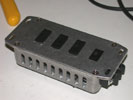
By flicking the various switches on the front of the load box, we are able to connect the power resistors inside in various series/parallel combinations, allowing us to present the panels with a load that varies between 0.5 and 14 Ohm. For a full sized panel, other resistances would be needed, as well as much beefier resistors to handle the power.
|
|
|
In order to characterize the I-V curve of the test panels, we applied different loads (from < 0.5 Ohm to > 20 Ohm) to the panel and measured the voltage across its terminals. A weather station at CRREL records the insolation received by a horizontal surface, which allowed us to subsequently determine the panel's efficiency.
|
|
|
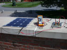
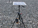
More systematic testing was necessary to determine the panel's efficiency and I-V characteristics with varying angles of insolation (that is, at different angles to the sun). This angle testing was accomplished with this setup. The panel is mounted on a camera tripod, and turned to different angles to the sun. The box with the switches is our load box, the switches permit various series and parallel combinations.
|
|
|
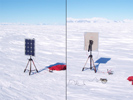
Jim Lever brought the 12-cell test panels with him to Antarctica during the 2004-2005 season. Using the setup shown here, he was able to better quantify and validate our estimates of how much power is available due to reflections and scattering by the near-infinite snowfields of the Ross Ice Shelf and Antarctic plateau. Based on these measurements and some further modeling, we estimate some 40% of the robot's power will come from snow reflections, even on those panels not facing the sun! A formal writeup is awaiting publication.
|
|
|
Here is data from the testing we performed to characterize the Current-Voltage curve of the 12-cell test panels at various angles to the sun. On the whole, our panels' overall efficiency is about 18% with our construction methods. Because the quality of text degrades in these tiny images, a full-sized image can be found here.
|
|
|
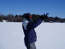
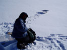
In rather stark contrast is the initial testing done during the winter of 2004, which was used to develop a model of the insolation available to a panel sitting in the midst of a infinite (or at least very large) snowfield that reflects and scatters the incoming sunlight. An important piece of data when developing that model is the angle of the sun above the horizon, measured here with a crude sextant.
|
|
|
As one can see from this picture, this kind of testing was rather cold work, when temperatures in the middle of the day barely reached 10 degrees above zero!
|
|
|